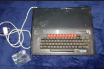
A while back I bought a rather ragged looking BBC B with a broken case and circuit boards hanging off it. It was not a pretty sight.
The first system actually came from a sound producer setup since it was painted black and had a Boss logo on it music roms etc…
At the time I was a bit over zealous , plugging it in and turning it on. There was the ubiutous continuous tone from the speaker… then shortly after some blue smoke! I had coitted the cerdinal sin of not checking for the dreaded Rifa caps. There it was in all its glory, fried to hell. Ordering a cap replacement kit I fixed up the power supply easily and re-installed it back into the unit. The same as before with the continuous beep. That was a good thing in a way since it has not got worse! The unit has a ROM extension board that held a bunch of music chips. Copying these onto disc from an EEPROM programmer confirmed what they had on them and I still have them in a box if anyone’s interested. The expansion board was an easy removal and a tidy up, sold that seperatly as it only had passive components and looked in good order. The idea here is to eliminate all the stuff that is not needed on the machine, divide and conquer.
Testing on a scope shows a string timebase signal and the reset is toggling from low to high.
That eliminates the following:
- Power supply
- Clock circuit
- Reset circuit
- Keyboard (as the reset can be triggered fine)
The next step is to see what is going on with the data and address bus. When the reset pin toggles from low to high the CPU should read the reset vector from address #FFFC the address stored in that location will be the start of the reset routine that has been defined. The challenge is to try and capture the address that the CPU is putting on the address lines during the reset.
Firstly a bit about the venerable 6502. It has the following general characteristics:
- Address Bus: 16-bits
- Data Bus: 8-bits
- 1 X 8-bit accumulator register (A)
- 2 X 8-bit index registers (X and Y)
- 7 X processor status flag bits
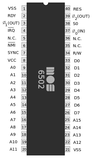
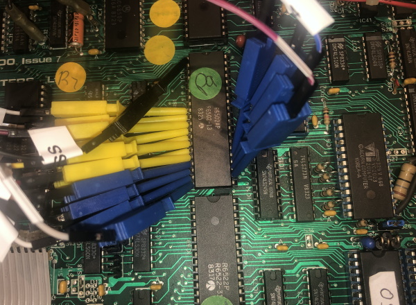
The idea here is to trigger the reset of pin 40 using the keyboard and hooking up a logic analyser to the bottom 8 lines of the address bus. The reason there will only be 8 lines attached is that my analyser only has 10 probes and we are only interested in the the lower lines so try and see the #FFFC pattern, which in binary is 1111111111111100 If we can see the CPU jump to that address in the logic analyser capture then we know the address decoding is working fine. We can then turn our attention to what is on the data bus.
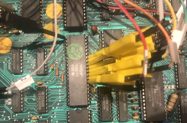
Logic Analyser setup
I am using a Hanteck Oscilloscope and Logic Analyser. It is a cheap unit and very basic but it has come in useful doing some debugging. I have learned a lot from one of my all time favourite YouTube channels Adrian’s Digital Basement, who put out a video on this unit (the one just the oscilloscope part at least) Check out the video and subscribe!
The issue with cheap test equipment for MHz range devices like 8-bit computers is the bandwidth they offer and the bad triggering. These devices do all the processing in software and do not store anything in fast memory within the device themselves. Therefore there is a big limitaton on USB bandwidth and processing. Still, let give it a try and see if there is any life left in the unit.
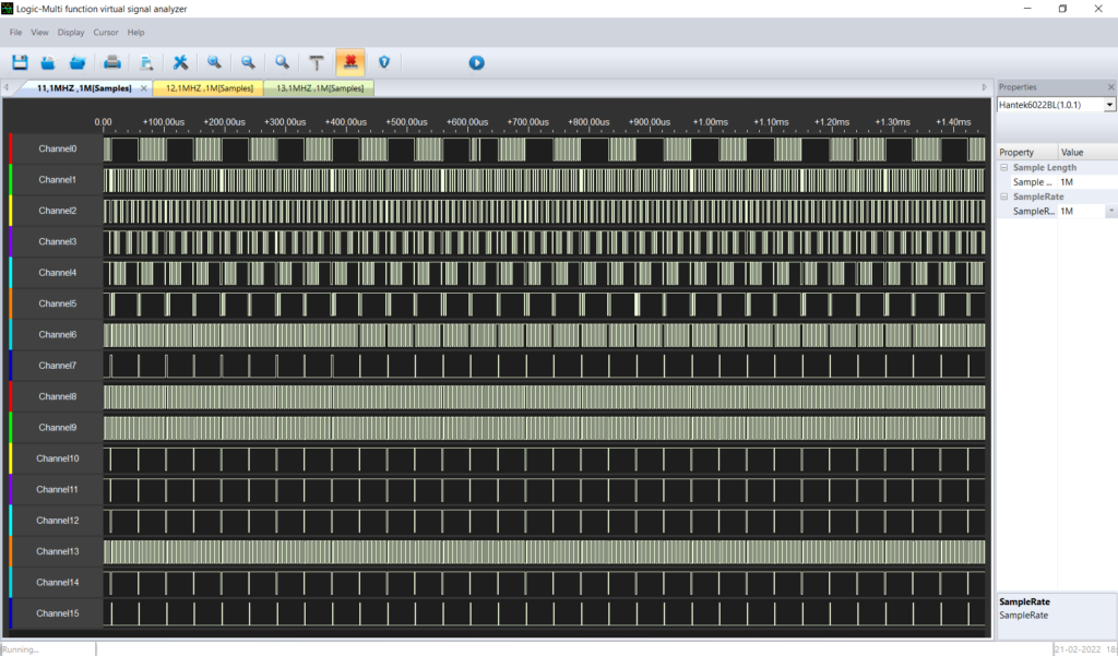
That the data lines added connected. Time to power it up and take a reading
It seems from here that D0 is possibly locked high, which is not good. There could be something on the data bus that dragging it high, like a bad mux or buffer IC.
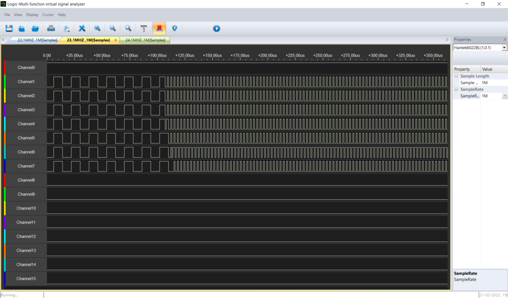
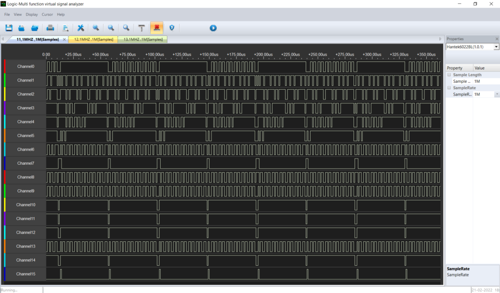
Now for the address lines:
Lets power that up and see:
There is lots of activity on the address bus here. At this point I dont seem to be able to set a trigger on the device. That makes it tricky to capture the exact startup session. Zooming in whtin the app and moving to the left we can see some of the startup sequence:
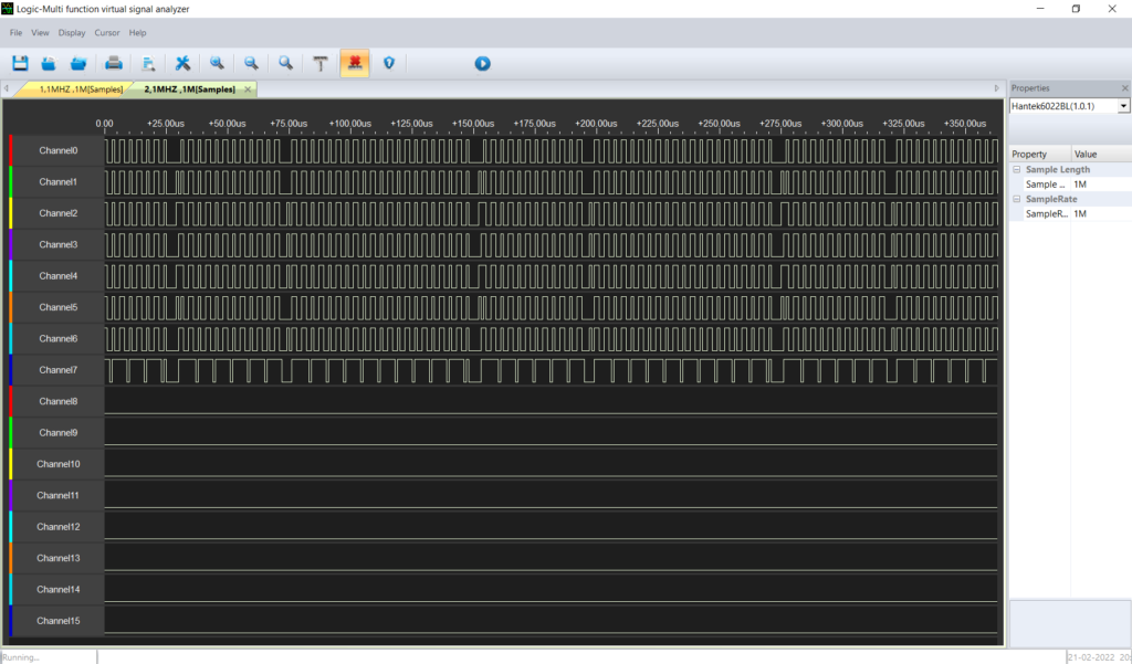
Really, I should try and convert these states to their HEX values. That is something more expansive devices do. Annoying since this is just software at the end of the day. The app for the analyser is not great, very basic. There are some public domain apps that are compatible, so I will have to take a look at these.
That is where I have got to with this. I have been trying to track down the possible data bus issue with no luck. Ideally I need a good solder vacuum to remove some logic chips and get a better look.
I did look at the data bus connected to the OS ROM.
It actually looks different to the oroginal CPU data bus reading. Bit0 is doing stuff. I has assumed they were copnnected but perhphs there is a buffer in the way as I mentioned before. I need to get the schematic out and trace the connections through.
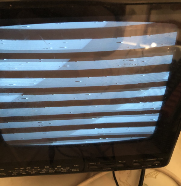
Video
As a side note the video output of this machine is like this
Donor unit
Reading the repair guides and watching videos of others battling BBC Micros, it has become clear that the only way I am going to make progress is to start replacing components with known good equivalents. Enter a donor machine. I found on eBay a unit that was listed as for part with a description that it beeped when turned on and that no further testing was done. It turns out that it was in amazing condition for its age, a sweet little version 4 board with a full stack of ROMs. I avoided the desire to plug it in and this time took a look at the power supply. Ah ha! So this had a blown Rifa cap, or at least one with bits missing! Never a good sign. Swapping in the other known good power supply I was amazing to see that everything worked! Even the powered disc drive and some of the game discs provided booted right up! God I love these machines! If you have a good one then it tends to last. So now comes the task of eliminating the broken components to try and find the cause of the problem on the original machine.
The intention here is to fix both of them, or at least have a good idea of what is wrong with the original unit, other than the terrible black pain job, broken case, blown power supply and hanging off ROM expansion board!