There are numerous keyboard designs out in the wild. A particular type discussed here is the membrane keyboard, specifically the one designed on a single sheet of material (usually translucent plastic) presenting two carbon contacts for each key. When a carbon plunger is pushed down onto these contacts a circuit is made an the key press registered. These are distinct from the dual sheet membrane type that have upper and under carbon contacts that when pushed together make a circuit.
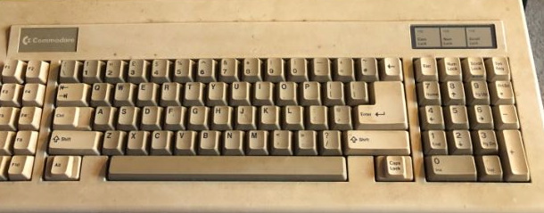
Keyboards made like this are not the most satisfying to use as they do not tend to have much feel. They are not as common as the dual layer type but still crop up from time to time. The information and tips presented here are for a Commodore PC10 keyboard, which seems to use the same mechanism as the Commodore Amiga range. Reparing this keyboard is a must as they are rare and expensive, especially in working condition.
Condition
The keyboard here was very dirty cable was intact and not damabged. Connector, of the od style XT type was also good.
Initial tests seemed enconraging, able to set the time on an XT machine but… No enter key! Ah, that could be tricky, a few keys not working here. If a few odd keys didnt work then fine but Enter? Well thats a serious issue, especailly since this partculatr kyboard only has a single Enter key.
Construction
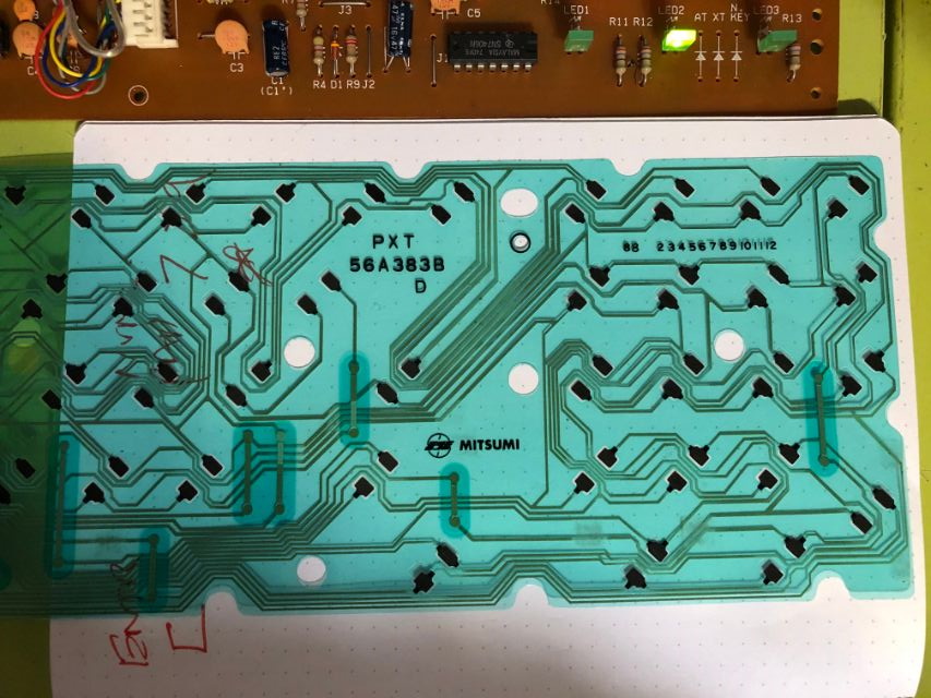
Keys are grouped together with thin wires going from carbon pad to carbon pad. That actually makes diagnostics quite easy. Each group of keys are routed out to the ribbon connector, offering a matrix that is then scanned by the decoding circultry.
Here are some steps for diagnostics.
Step 1 – Find the bad ones
Press each key and write down the broken ones
Step 2 – Open up the keyboard
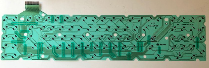
Lay out the membrane with the carbon pads pointing up. I initially found that the key layout was a mirror image, making things a bit tricky. Then had a think and worked out a better solution.
Identify the location of keys on the membrane and mark some keys with a pen, so you can easily identify where they are.
Step 3 – Check contacts
Now that the membrane is visible, and you know what contacts are which keys. You can then use some jumper wire to bridge the connection and wiggle things around to see if the contact is dirty. For each offending key identified in step 1 find the contact, squirt some contact cleaner on it and then wipe off the excess. Use the wire and see if you can get any hits for that key. If you are lucky, you might have already fixed it!
Step 4 – Check the plunger
It is also a good idea to clean the plunger contact, as this is carbon and might be worn or dirty. The carbon here is generally on a U shaped bit of plastic or even a spring, designed to spread and make good contact with the carbon pads on the membrane. A good can of contact cleaner is all you need.
Step 5 – Further diagnostics
If you are still here, then things are getting a bit more serious. For the broken keys, you need to visually find the first contact in the string. Using a test meter in resistance mode or a continuity tester, you can then place one of the leads on the first carbon pad and trace to the next one in the string. Each of them in the sting should show correct continuity with the first one and if all of them check out then move the other lead to the ribbon cable. It can be very dense here and difficult to see, but if you gently swipe the lead across the connector you can sometimes see the continuity here and if that is the case then that string is likely to be fine.
When diagnosing this keyboard that is what I found with the first string of carbon contacts checking out fine. Time to test the other contacts for the broken keys.
Here it was obvouoslt very quickly that there was a break in continituty between the 4th and 5th key in the stirng. It was not at all obviously visually that this was the case but the test meter was certinaly showing a break.
Check FROM 5th to ribbon?
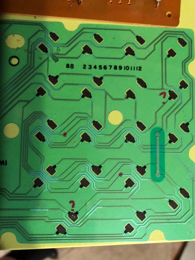
The image above shows two keys linked together with a trace. The top question mark is fine and there is continuity right back to the edge connector. When You move to the lower quesiton mark there is no continutiy! Ah ha! There must be a break between these two key contacts. It is not visible, even with a mignirfiny glass, but it is broken for sure! Both these contacts when connected together should make the tyester beep but nothing.
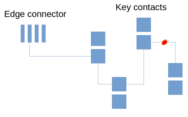
Above is a diagram showing the setup. Each contact string needs to connect back to the edge connector. If it does not, then the string has an issue. In this case, a break in the connection between the last two contacts.
So how do we fix this?
Step 6 – Painting with wires
For these type of plastic membrane is it not practical so solder anything to the carbon contacts. It simply will not adhere, and you are likely just to melt stuff and probably make it beyond repair. What is needed is a solution that does not involve heat and will stick to the plastic without damage. It will also need to be small enough to thread through the tight space between carbon contacts.
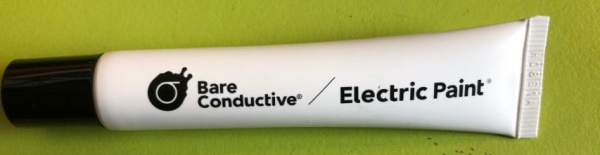
Conductive paint is the answer here, it can be drawn onto the plastic and stick in place, enabling repairs between any broken contacts.
It may not be possible to fix any broken strings that are between the ribbon cable and the first contact in the string. If that is the location of the failure, then it may not be possible to draw a conductive trace right back to the ribbon cable.
In such a circumstance it may be possible to fix this with a bodge wire soldered onto the ribbon cable connector and then sticking the other side of the wire to the membrane. The wire would need to be very thin and flexible for it to work. Once in place, the repair would then make it tricky to perform any further repairs without risk to dislodging the bodge wire.
The unit shown here was bought from eBay as part of a rather sad looking Commodore PC10, missing the top of the case with the PC speaker handing off… The keyboard appeared to be dirty but intact, however you never can tell when you buy things like this when the description does not guarantee anything. Let’s take a chance.
Firstly used the paint to draw a thin line between the two contacts, but that did not work. There WAS continuity, but the electrical resistance was in the 100’s Kohm range, which is not great. So the alternative is to use the paint as a cold solder equivalent:
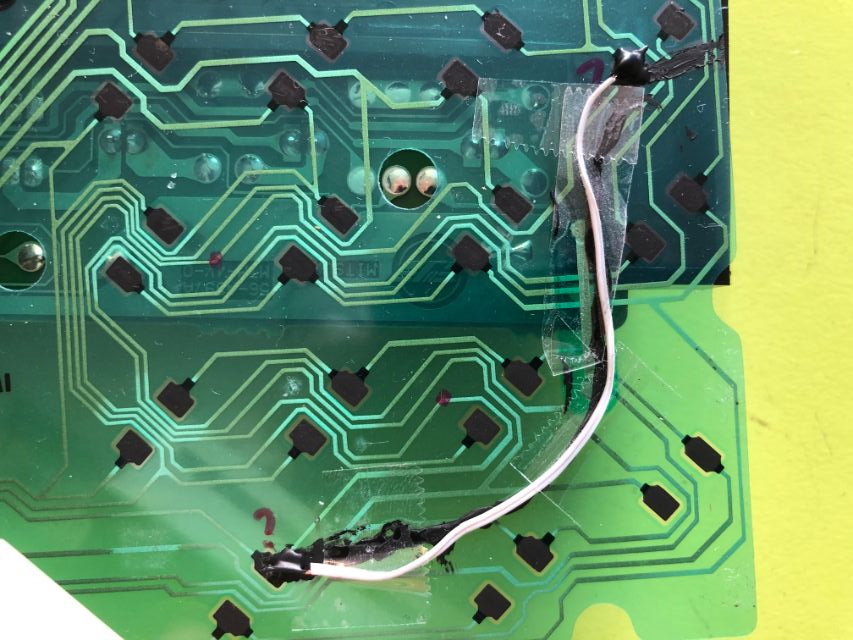
The wire here is flexible and tiny, stuck down with tape. Yeah, I know it looks horrible but in fact the paint acts as a good adhesive, they tape it to prevent it from moving around when rebuilt.
Testing the above and it WORKS!
That’s awesome! A cheap fix and another ancient computer part rescued!
Step 7 – Keys
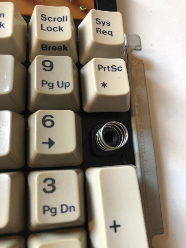
There was also an issue with the minus key on the keypad. It was not working, but the tracks looked OK. Turns out that this plunder is totally ruined:
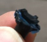
The end of it was snapped on one side, meaning it was simply mashed into the pads below without making contact. Interestingly enough, I found a replacement on eBay, designed for an Amiga keyboard:
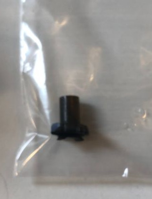
Came quickly and was a easy to plug back into the keyboard:

Keyboard restored!
Result…