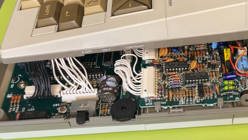
The lovely NEC 8201A machine is well engineered but it still had the curse of an internal state battery that is non-user-servicable. It is good that they are unlikely to leak BUT they are soldered to the board!
ARGH… WHY Nec? In fact WHY any manufacturer would you do that?
Reminds me of the terrible soldered DALLAS RTCs on old PC boards. Terrible idea.
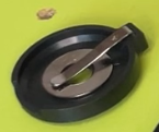
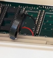
The 8201 is guilty of such crimes. The battery is soldered and looks like this:
Urgh… Nasty… At least it was not one of the leaky things.
What we are going to do? A replacement battery can either go directly into where the above battery is OR under the back cover where it is easier to access? In my box of bits I have some nice CR2032 battery cell holders:
I also have some CR2032 cells that can be used which should have enough voltage to keep the thing alive for long enough. There is a charge port on the back of the NEC that takes 8.5V and this can charge the internal battery, as it is a NiCad. Using a normal CR2032 call would be a bad idea if you were going to charge since it might not like the reverse voltage.
Adding a diode in series would stop this but then there is a voltage drop across it that would compromise the time it would work for.
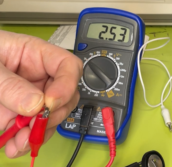
With the diode:
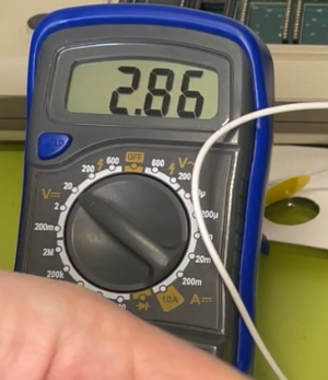
Without the diode:
A 0.3v drop would not be good when the original voltage of the NiCad is 3.6v and we are trying to get away with a 3v cell.
Enter the LIR2032 cell, which is the same physical package but is rechargeable! Perfect. That would allow us to eliminate the diode, keep it small and easy to replace AND rechargeable.
A pack of 5 LIR2032 cells has been ordered but for now will just use a CR2032 and not plug it in.
Lets get chopping!
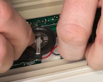
Using some sharp side cutters we can remove the battery but try and keep as much of the solder tags as possible:
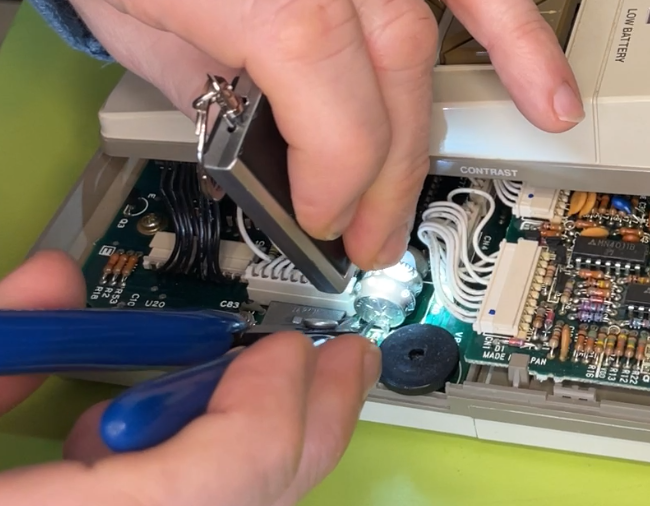
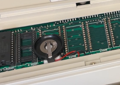
With the battery removed there is some nice space and enough of the contacts left to solder onto:
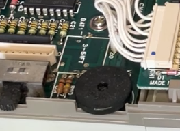
The + is marked on the board in case you forget to make a note of it.
Get a couple of black and red wires and solder them into place:
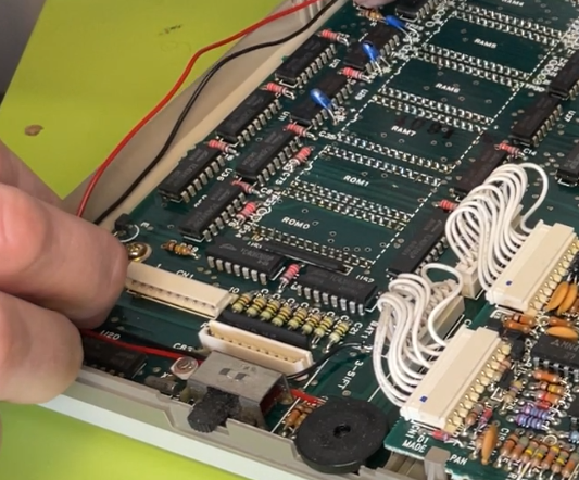
Using some hot melt glue to secure the wires and then route them next to the RAM7 position on the board. From here is can be pocked though:
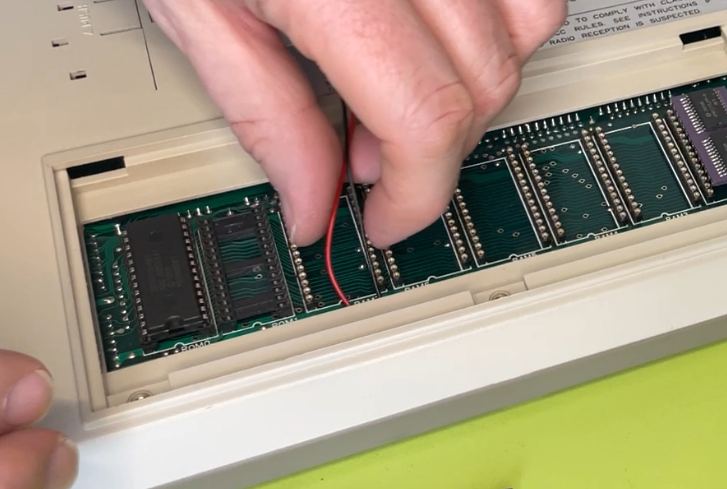
The intention is to mount the cell holder on the RAM7 slot to keep ROM1 free and move as much away from RAM2 as possible. Maybe there would be more memory added in the future? Lets hope so.
Soldered and ready to be mounted:
A couple of layers of sticky backed foam pads and another smaller one on the back of the holder is enough to nicely secure it without interfering with the back cover. Neat!

Testing can be begin.
When the LIR2032 cells turn up that will be swapped into it.
Then will build an 8.5v adaptor and check the charge voltage on the cell holder.
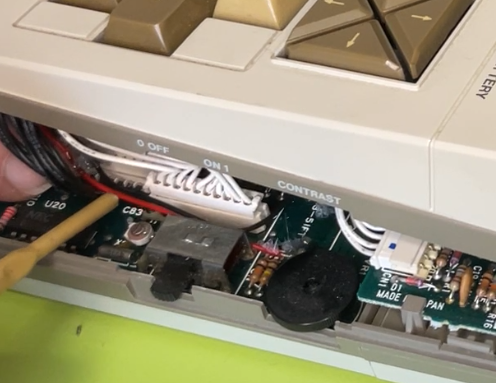
Warning about cable routing. It was a bit painful getting the thing back together again as the plugs for the keyboard were impeeded by the new cables. They needed to be moved away from the keytboard socket a bit.
With that done:
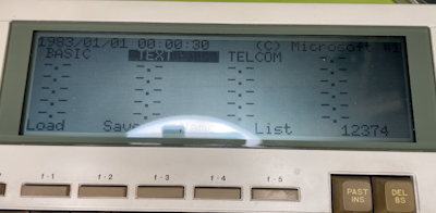
All looks good… Well mostly…
The RAM figure seems lower than before!
When messing around with the back cover I must have disturbed the RAM module:
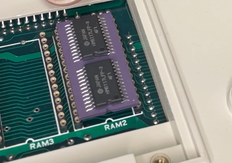
Following a REALLY scary bit where I bent the pins badly the RAM was restored:
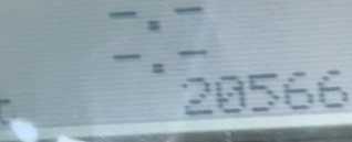
Fhew! All done