We take a look at a strange little computer with a tiny 9″ screen
The screen shows serious burn-in.
It says “OEM” on the front, has 2 3.5″ floppy drives but only a single 15-pin D
connector on the back… Strange.. What is this thing?
Firstly lets take the thing to bits and have a closer look. The bottom contains a couple of screws at the back:
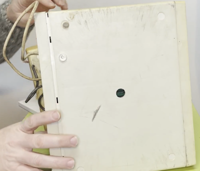
With those removed you can wiggle the rest of it out. There is a circuit board and a separate dual drive tray:
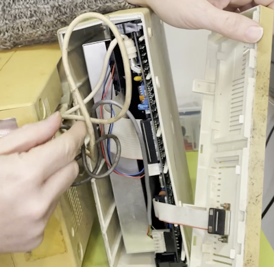
The connectors are:
34-pin floppy connector, that is encouraging since this could be a standard type!
4-pin power, looks like a standard floppy power connector, these typically have +5 and +12 volts
2-pin video connector, most likely composite video! Nice…
15-pin connector. Not sure about this one. It terminates to a 15-pin D on the case, most likely for a keyboard or printer
The connectors come off ok but they are corroded:
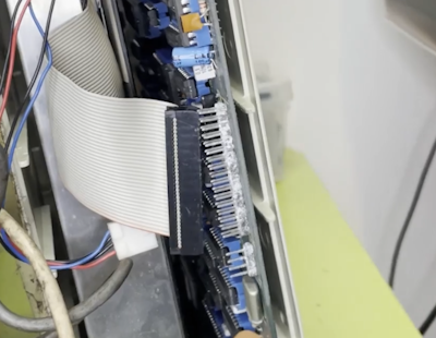
Nasty looking white gung on these but the pin themselves look kind of ok. Really weird stuff, not sure what this is. Could be the plastics breaking down.
The circuit board comes out easy when unplugged:
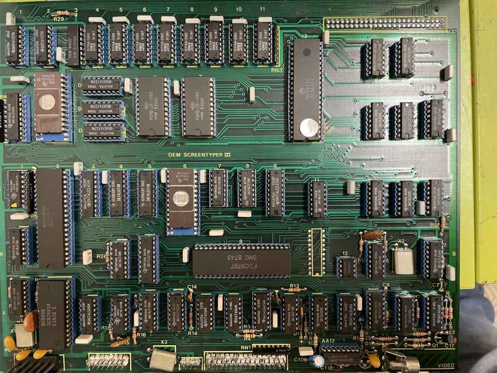
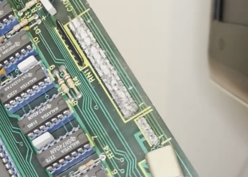
Amazing looking board and you can see OEM SCREENTYPER III right in the middle so the mystery is partly solved. It is a word processor. Most likely the system plugs into typewriter style printer and this can be used to edit the text.
All the ICs are socketed which is amazing! If only every machine had this… Also they are blue! Extra nice…
Major parts
Here is an audit of what is there:
- Moztek Z80 – CPU
- Motorolla – MC6845P Display controller
- FCD9797 – Floppy controller
- SCN2661A – UART controller
- MSM2128 – 2048-WORD x 8-BIT C-MOS STATIC RAM (2 of these)
- M3764 – 64K bit fast page CMOS DRAM (8 of these)
- 2732AJL – EPROM (2 of these)
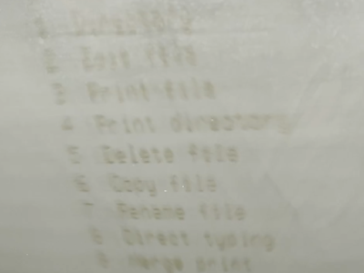
Doing some digging it seems that this could be a system running CP/M dedicated to word processing. The terrible screen burn does hint at that:
System diagram
So the system can be broken down into the following logical blocks:
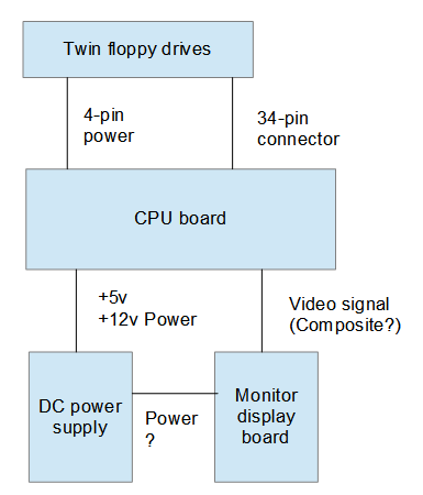
Not powered it up so cant see what the power connection is from the supply to the display board. It could possibly be just 12v. Will need to take it to bits to see.
Floppy drives
The floppy drives are MD 353 and there are two on the same ribbon cable. They seem to take the standard 34-pin connector and also the standard 4-pin power. These need to be tested to see if they can be recognized by anything.
They have a nice drive ID switch visible through the case:
CP/M Machines typically require a floppy and the ROMs are only there for the basic boot code, so the question is, where on earth would you get a boot floppy for an obscure word processor? Could be tricky…Certainly Google is not much help so far.
Connections
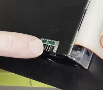
The underside of the monitor shows the following:
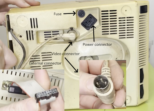
It is not clear what connects to the 15-pin D but most likely a keyboard and printer. I have been trying to find an example online but with no luck.
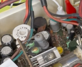
Power
Looking in more details at the board the following seem to be the correct power connections:
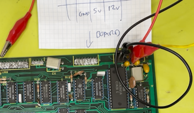
Of the 6 pins only 3 are used. These appear to be:
- Pin 1 = N/C
- Pin 2 = N/C
- Pin 3 = GND
- Pin 4 = +5V
- Pin 5 = +12V
- Pin 6 = N/C
Continuity tests on the board to the appropriate pins of many of the logic ICs suggest that this is the case:
Testing is using a PC power supply that has a nice 5v and 12v power supply
Hooking it up to testing.. Well… It didn’t go amazingly well:
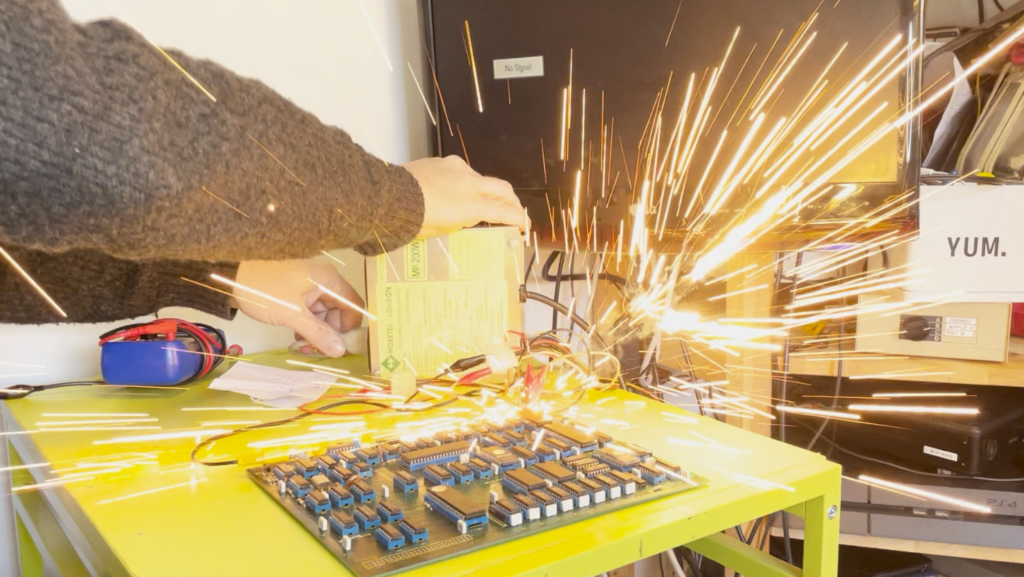
There is a little tantalum decoupling capacitor that decided to go pop:
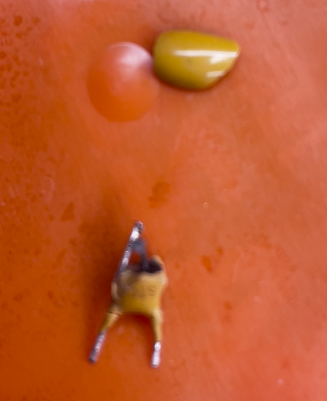
Not much left of it with burn marks on the rug and table… Oh well!
It seems to be between 12V and ground, I guess to offer decoupling.
Second power
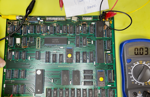
With the capacitor removed it was time to see if there is still life on the board using a logic probe.
Using a current limited 5V supply connected up and no 12v it was time to probe around. There is numerous high and low logic levels on the board and all looks consistent. All except for the CPU which seems to show all kids of weird behaviour. It is tricky when using a probe, the next step is to use an oscilloscope to look into the board itself.
Connecting to pin6 on the Z80, which is the clock input, the tone from the probe was all over the place. It could be that the frequency is too high, it is not clear.
Tube
A viewer asked for a closer look at the tube:
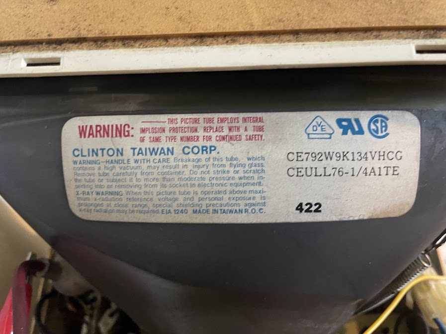
CE792W9K134VHCG
CEULL76-1/4A1TE
Powered up tube
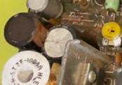
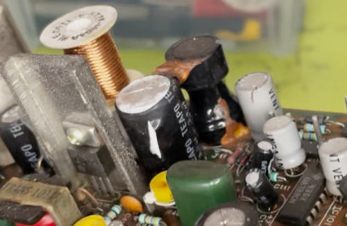
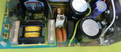
With 12Vs applied to the set and minimal current there was smoke from one of the caps C427.
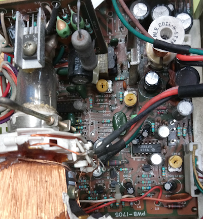
Here are two very hir res images of the circuit:
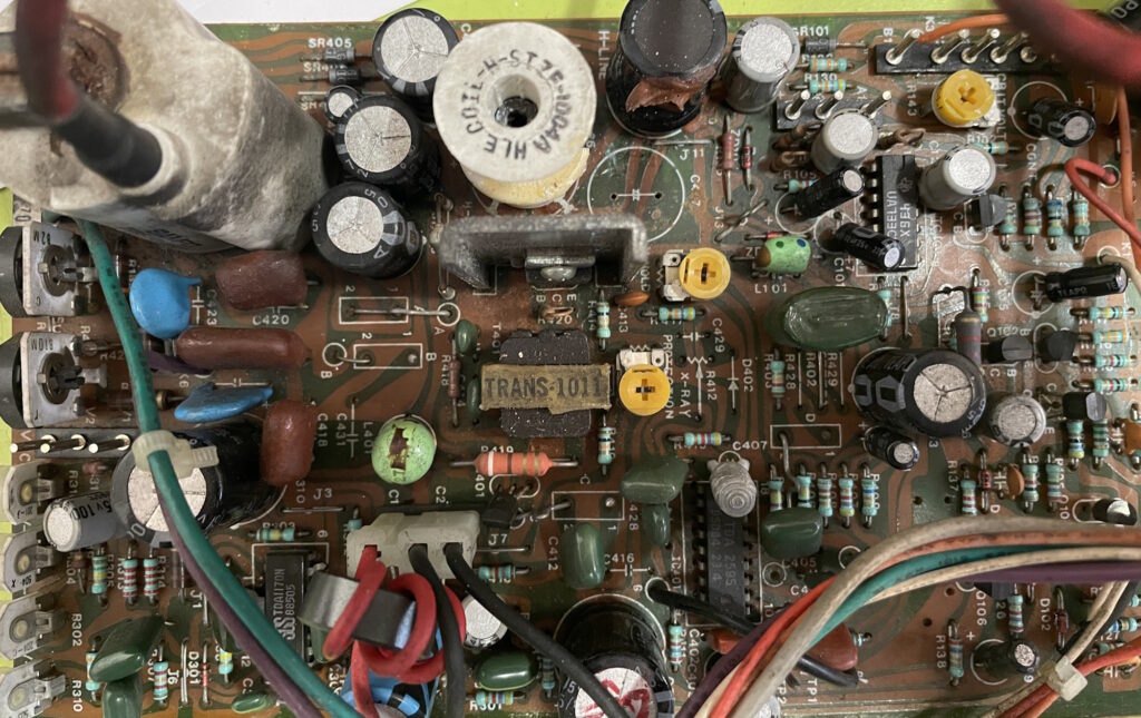
Right-click and open image in new tab and you can zoom right in.
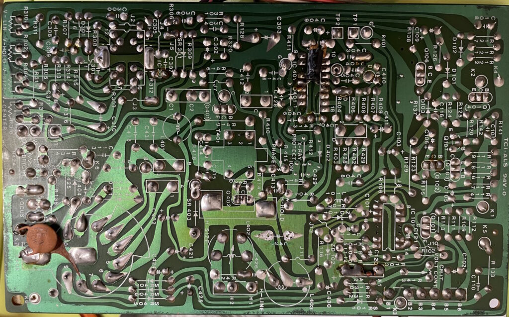
Right-click and open image in new tab and you can zoom right in.
There are three types of caps marked on the back of the board:
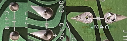
Left: Capacitor
Middle: Electrolytic
Right: The on that blew. There is no polarity marking and it could be a bipolar?
Need to know what this is before replacing it.
Before:
After:
Got new caps, finally. 3.3uF 50v ones but they are MUCH smaller. Lets hope they work.
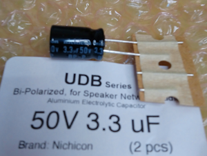
Nichicon but lets hope they work for a bit.
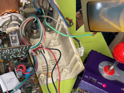
In circuit now:
With a bit of reassembly the test shows this:
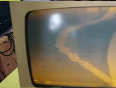
Amazing! It is am amber screen. The input here is the normal game console input:
A tuning did not do much but I think the vertical sync was ok. It is not clear if the signal is even compatible with this monitor, it could be anything but you can see something there, which is a result.
The PSU should be an easy fix. Replaced the Rifa caps:
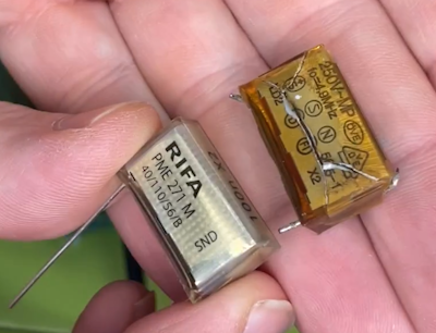
Not current tested.
Next steps:
Dismantle the monitor and clean the case
Test the PSU
Use an Oscilloscope to view the clock
See if the CPU is stuck in reset
See if there is any Address and Data bus activity
Test the logic ICs
Stay tuned…