If you have a bunch of 4164 chips lying around how do you know if they work? You can buy a tester, for a fortune. OR… If you have an Arduino Nano lying around, a bread board and some wire then just make one! How hard can it be?
Well it turns out it can be a little tricky. There are many circuits and Arduino sketches online but just about all target the Arduino Uno. Thats all fine but if you have a Nano, in many ways a better fit for this, then there are challenges.
The IC we will be testing is the 4164, which I have a bunch of that came from an old Apricot PC expansion card that happened to be entirely socketed! (A rare thing indeed!) Here is the pinout:
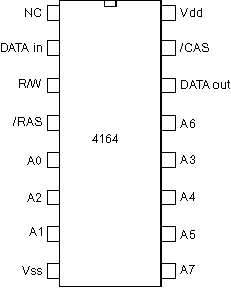
Here is the summary of the chip.
65,536 x 1bit
8 x Address lines giving 256 bits
To read/write data you need to set the address on both ROW and COLUMN (CAS) addresses.
First set the address and strobe the ROW pin.
Next set the address and strobe the CAS.
Now the DATA In can be stored in memory when strobing the RW (read/write) pin
Notice there is a DATA In and DATA Out pin.
There is an amazing turotial that can be found here
Arduino
There were a few tutorials online showing a sketch for Arduino that can be used to test these ICs. Most of them however were for the Uno and the pinout naming is a bit of a nightmare to be honest. I found it very confusing. I wanted to use a Nano as it would sit nicely on the breadboard.
Eventually I found a nice diagram showing the Nano:
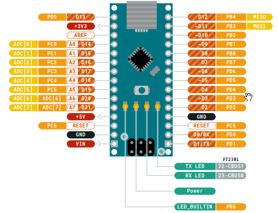
That was useful in updating the pinouts of the Arduino sketch.
Here is an adapted sketch based on one I found online, with a little reworking:
#include <SoftwareSerial.h>

#define DI          15  // PC1
#define DO           8  // PB0
#define CAS          9  // PB1
#define RAS         17  // PC3
#define WE          16  // PC2

#define XA0         18  // PC4
#define XA1          2  // PD2
#define XA2         19  // PC5
#define XA3          6  // PD6
#define XA4          5  // PD5
#define XA5          4  // PD4
#define XA6          7  // PD7
#define XA7          3  // PD3
#define XA8         14  // PC0

#define M_TYPE      10  // PB2
#define R_LED       11  // PB3
#define G_LED       12  // PB4

#define RXD          0  // PD0
#define TXD          1  // PD1

#define BUS_SIZE     9

/* ================================================================== */
volatile int bus_size;

const unsigned int a_bus[BUS_SIZE] = {
  XA0, XA1, XA2, XA3, XA4, XA5, XA6, XA7
};

void setBus(unsigned int a) {
  int i;
  for (i = 0; i < BUS_SIZE; i++) {
    digitalWrite(a_bus[i], a & 1);
    a /= 2;
  }
}

void writeAddress(unsigned int r, unsigned int c, int v) {
  /* row */
  setBus(r);
  digitalWrite(RAS, LOW);

  /* rw */
  digitalWrite(WE, LOW);

  /* val */
  digitalWrite(DI, (v & 1)? HIGH : LOW);

  /* col */
  setBus(c);
  digitalWrite(CAS, LOW);

  digitalWrite(WE, HIGH);
  digitalWrite(CAS, HIGH);
  digitalWrite(RAS, HIGH);
}

int readAddress(unsigned int r, unsigned int c) {
  int ret = 0;
  /* row */
  setBus(r);
  digitalWrite(RAS, LOW);
  /* col */
  setBus(c);
  digitalWrite(CAS, LOW);
  /* get current value */
  ret = digitalRead(DO);
  digitalWrite(CAS, HIGH);
  digitalWrite(RAS, HIGH);
  return ret;
}

void error(int r, int c)
{
  unsigned long a = ((unsigned long)c << bus_size) + r;
  interrupts();
  Serial.print(" FAILED $");
  Serial.println(a, HEX);
  Serial.flush();
  while (1)
    ;
}

void ok(void)
{
  interrupts();
  Serial.println("");
  Serial.println(" OK!");
  Serial.flush();
  while (1)
    ;
}

void fill(int v) {
  int r, c, g = 0;
  v &= 1;
  for (c = 0; c < (1<<bus_size); c++) {
      Serial.print(".");
    for (r = 0; r < (1<<bus_size); r++) {
      writeAddress(r, c, v);
      if (v != readAddress(r, c))
        error(r, c);
    }
    g ^= 1;
  }
}

void fillx(int v) {
  int r, c, g = 0;
  v &= 1;
  for (c = 0; c < (1<<bus_size); c++) {
      Serial.print(".");
    for (r = 0; r < (1<<bus_size); r++) {
      writeAddress(r, c, v);
      if (v != readAddress(r, c))
        error(r, c);
      v ^= 1;
    }
    g ^= 1;
  }
}

void setup() {
  int i;

  Serial.begin(115200);
  while (!Serial)
    ; /* wait */

  Serial.println();
  Serial.print("DRAM Test program ");

  for (i = 0; i < BUS_SIZE; i++)
    pinMode(a_bus[i], OUTPUT);

  pinMode(CAS, OUTPUT);
  pinMode(RAS, OUTPUT);
  pinMode(WE, OUTPUT);
  pinMode(DI, OUTPUT);

  pinMode(M_TYPE, INPUT);
  pinMode(DO, INPUT);

  digitalWrite(WE, HIGH);
  digitalWrite(RAS, HIGH);
  digitalWrite(CAS, HIGH);

  /* jumper set - 4164 */
  bus_size = BUS_SIZE - 1;
  Serial.print("64Kx1 ");

  Serial.flush();

  digitalWrite(R_LED, LOW);
  digitalWrite(G_LED, LOW);

  noInterrupts();
  for (i = 0; i < (1 << BUS_SIZE); i++) {
    digitalWrite(RAS, LOW);
    digitalWrite(RAS, HIGH);
  }
}

void loop() {
  interrupts(); Serial.println("Step 1"); Serial.flush(); noInterrupts(); fillx(0);
  interrupts(); Serial.println("");Serial.println("Step 2"); Serial.flush(); noInterrupts(); fillx(1);
  interrupts(); Serial.println("");Serial.println("Step 3"); Serial.flush(); noInterrupts(); fill(0);
  interrupts(); Serial.println("");Serial.println("Step 4"); Serial.flush(); noInterrupts(); fill(1);
  ok();
}
So using the Nano image and the IC pinout it is possible to wire up the breadboard with the correct jumper cables. A bit fiddly but you get there in the end. Here is the final mess of wires:
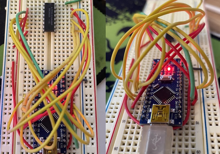
Once setup you can then use a normal terminal program. Set it to 115200 baud, insert the chip to test and then push the reset button. You do not need the Arduino IDE running.
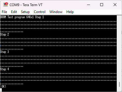
Makes we want to hook up my old amber screen terminal emulator but I will resist the urge…