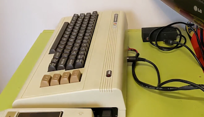
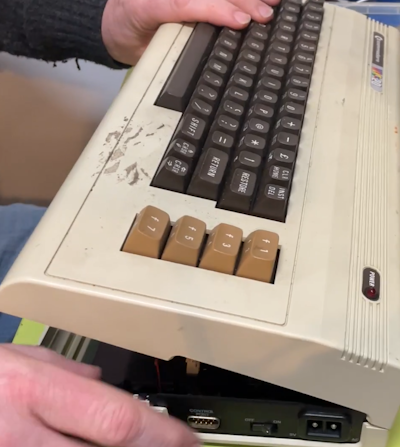
A nice little VIC-20 is in the collection but it is in poor shape cosmetically. However I think that it mostly surface stuff and that deep down it is a diamond that wants to shine!
It was in storage for quite a while and worked when it went in, but was dirty and a bit unloved. Getting it back out again it was still dirty but this time the power switch has failed. It was jammed solid and what made it worse was that it was stuck in the OFF position so no hope without a fix…
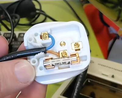
Firstly however the plug was removed as it was cracked and whoever attached it needs a lesson in wiring!
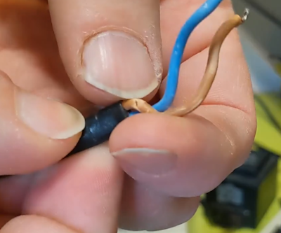
The leads were tinned but were far too long and the live cable was cracked. Cutting it off and trimming the leads to the right length:
Opening up the case is easy enough. Three screws on the base and a row is angled catches on the back. Take great care in lifting from the front of the case, like opening the bonnet (hood) of a car. Gently does it
There are 2 cables attached. One for the keyboard and another for the power LED. These are easily attached and massive kudos to Commodore, these cables are nice and long! Many other devices and computers are not like that with cables only just long enough and a real pain.
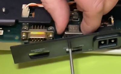
Once open there are loads of screws to take out to release the motherboard.
If you are looking at the power switch then take care to leave the screws along that edge in place as they hold the mounting bracket.
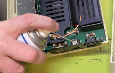
First thing to try was contact cleaner to see if the switch can be freed up
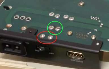
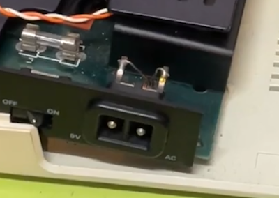
No luck here. Lets get the switch off to take a look. Turning the board over you can see 4 solder points.
The green circle shows the switch contacts. The red shows the mounting points that mechanically attached the switch in place.
All of these need to be removed with a solder sucker and iron
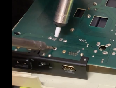
Ensure that you use plenty of fresh solder on there to melt what is there and allow you to remove as much as possible. Finally it is a good idea to use a soldering iron and slide a small flat blade screwdriver under the switch. A gentle wiggle can sometimes free the switch.
As mentioned it is important to keep the bracket attached for an long as possible. The power connector has an inductor attached to it and with the screws taken out it is only attached by that, meaning that it can be very fragile.
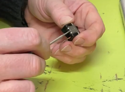
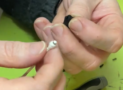
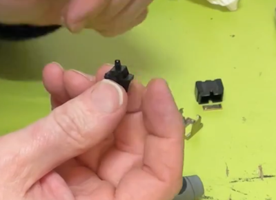
Once the switch is removed it can be examined and taken apart. The outside of it is simply a metal clamp that is bent around the body of the switch:
When opened up there is a simple rocker mechanism and a plastic plunger.
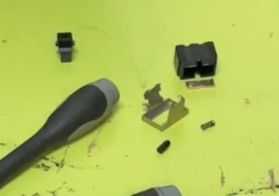
The plastic plunger is pushed by a spring inside the switch cover. In this case it was totally jammed solid. Removing the parts it was possible to use a cotton bud and some IPA alcohol to clean the inside of the switch rocker:
With the channel cleaned and the spring and plunger put back it moved quite easily which should be perfect.
Using some contact cleaner on the contacts in the switch completed that repair.
Reassembly is straight forward and soldering it back into the board resulted in a switch with nice action.
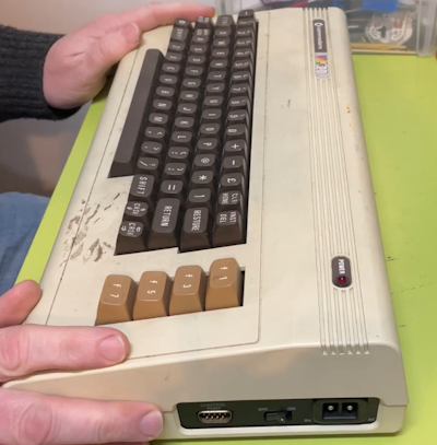
Next was the case.
The base seemed to be fine but the top was in a terrible state and was more than surface. It needs a deep clean.
The top case is going into the dishwasher on a intensive program but before that it is important to protect the labels. In the case of this VIC-20 there are two sticky labels on the top. To protect them find some normal labels and retrieve the backing material:
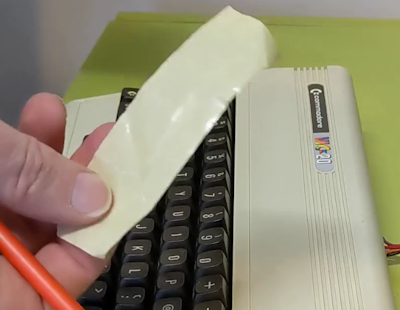
Using a pencil or pen place this over the label to protect and draw the outline. It can the be cut to shape:
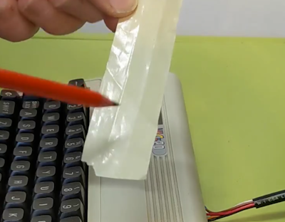
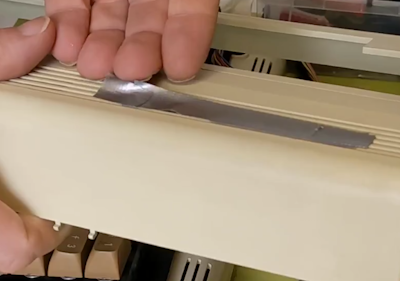
And stuck to a strip of strong tape:
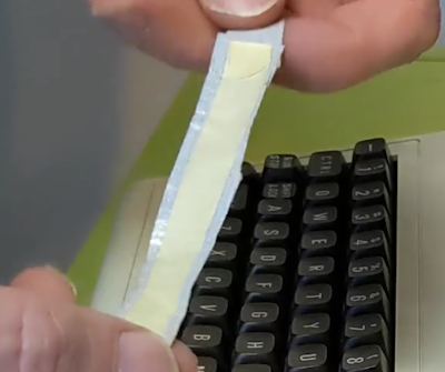
That can now be safely placed over the label before the whole thing is washed.
Used this method a few times and had good results. It is easy to remove after washing and does provide enough protection for the labels. Here is the cover just out of the dishwasher and just removing and excess water:
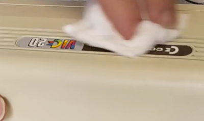
Clean as a whissle.
RF tuning
With the power switch fixed and the unit cleaned it is time to test. Normally this would be used with a monitor-SCART lead and that works nicely. However there is an RF modulator and in the past had great success with it. Testing it now however the monitor struggled to tune into it:
There is an automatic scan but no fine control on this monitor so perhaps others would work better. However, opening the modulator is only a single screw so lets have a look:
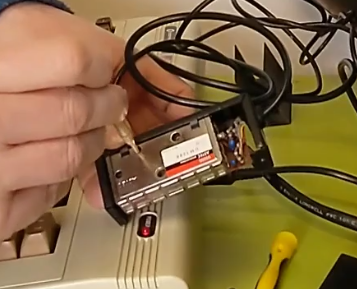
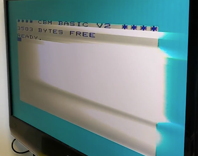
The position shown here is for the adjustment of the output frequency. Using the correct plastic screwdriver the picture can be make much better with a simple turn:
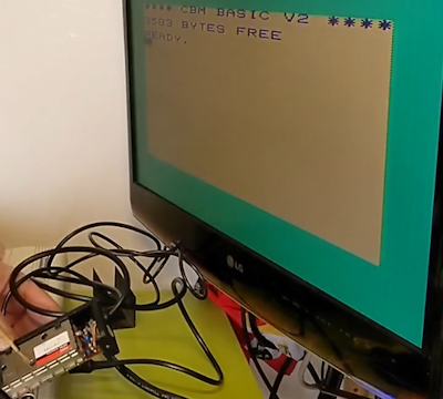
The picture is better and there is no audio buzz so that it an easy one to try. Much easier then messing with the tuning menus on the monitor… Especially when you don’t have the remote!
Testing the tape deck worked ok, saving and loading a simple 2 line BASIC program:
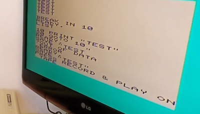
It is a useful thing as it tests both LOAD and SAVE
Another useful test is of the drive interface. Using an SD2IEC adaptor makes that super easy. You can load into the filebrowser and boot your favourite game (not much choice with an unexpanded 3K VIC-20!!!)
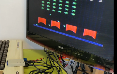
That’s it for now. A fully working, nice and clean VIC-20 ready for action!