A new challenge has come into the workshop (junkshop?)
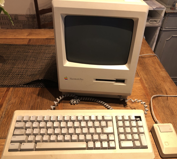
A classic Apple Macintosh Plus. That is one of those early square box Apples with the small black and white screen. Super cute and really a nice machine. Sure only black and white, not mega fast but for its time it did what Mac has done for years. You plug it in and it just works… Well in this case we will see if ‘just works’ is really thing. After all it is an old unit but does look intact. It was listed with a bunch of other things, mostly app Apples related. One of the best things here is that even if it did not work there was a bundle of stuff that wen be broken down or used in other systems. I love the old school mouse. Nice big chunky single button affair. With the original 9-pin D connector. It was compatible with the Apple IIc and Apple IIe with an adaptor. The keyboard is a really nice one, missing a key but the feel of it is lovely and clicky. Almost as nice as the Apple IIe sat near it.
Stopping messing about and plug the thing in!
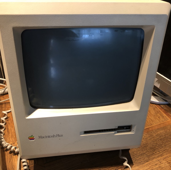
Oh… Well there was the Apple chime! So something is alive in there, but no display. Looks like it might be time to open it up and take a look inside.
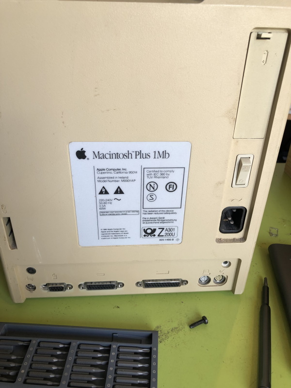
Just a few screws and a bit of jiggling about and it cames to bits easily enough. The first thing to check here is for a glow on neck of the tube. If there is no glow there is no show… The glow should be easy to spot and is the electron source for the CRT.
It goes without saying, but I will say it anyway, that mains voltages can kill. Anode voltages from a CRT can kill and make you glow in the dark. Be careful!
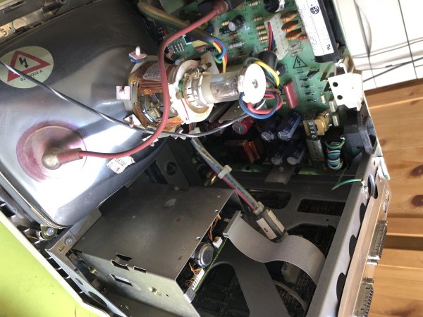
A closer inspection of the tube with the unit turned on shows something encouraging:
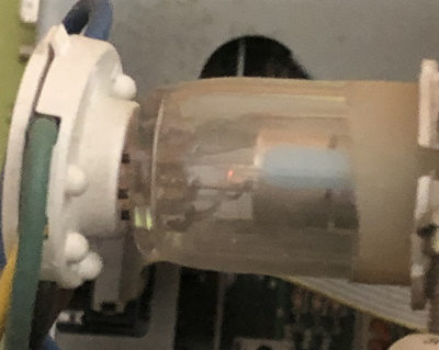
That tiny little orange glow is a good sign. There is life in at least some of the CRT control circuitry. Notice that at this point I have not done any cleanup and the tube neck is a bit dusty. I would recommend caution in doing anything too heavy handed at the start of any repair, expecially with a CRT.
Lets flip the swtich:
Ok so the display is blank but there IS life:
Nice! At least there is power and the board is starting up, at least to a point. Lets have a play around with the brightness control:
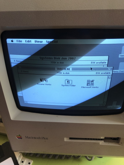
Inrteresting. So there is a raster, which is also a good sign. Means there is high voltage on the CRT and that will probably be ok. Perhaps an issue with the video level signal. There is no smell from the machine so lets leave it to heatup a little bit. Sometimes that reforms caps or helps dry joints work again, you never know. After about 10 mins still nothing. Tapping the side of the unit is not recommended BUT I was able to see some video frame data, slowing it right down and cropping it:
You can clearly see the system has booted off one of the system floppy discs that came with it! Thats a result… So perhaps it will come to life further as it heats up more.
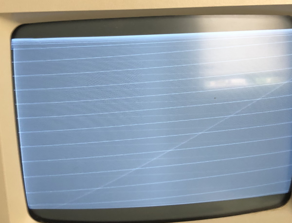
After another 15 mins or so the image snapped into glory:
the lines here are the 70Hz refresh of this screen and not coming up well on the camera. In reality the picture was rock solid… When it was visible. There was still the occational black screen for a few seconds so there is something nasty going on. Lets add that to the to-do-list. Speaking of a list here are the things to do next:
Test and clean the mouse
Test and clean the keyboard
Clean the case (it is complete but dirty)
Investigate the display issue
Review the state of the discs, At least one of them loads
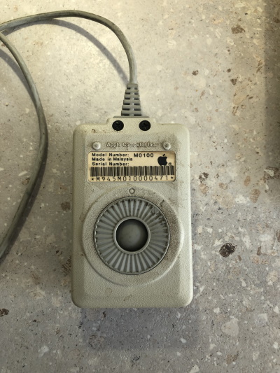
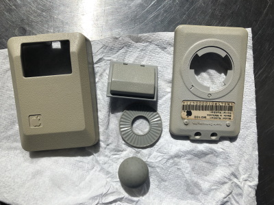
Mouse
The Apple mouse M0100 is a lovely thing, but in this state I dont really want to touch it:
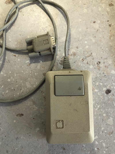
The motion worked and you can move around the screen but like most ball mice they quicky get rough and then stop working. The classic is they might work ok vertically but badly horizontally making the pointer behave in a really drunk fashion. Time to take it to bit and clean it.
There are only 2 screws for this to come apart. One tip here is to have some masking tape on hand for any labels on stuff you are going to wash and srub. In this case the label here needs masking. Opening it up reveals the retro goodness:
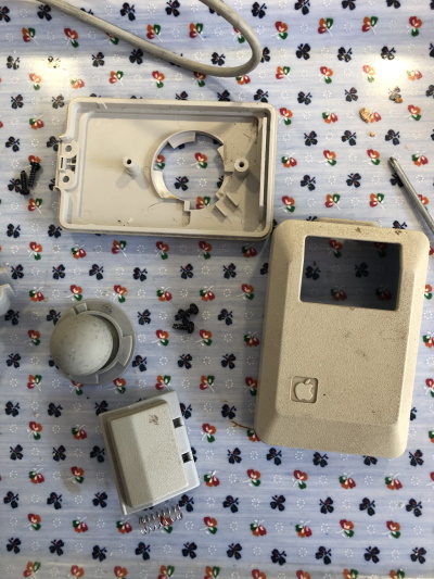
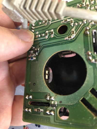
The circuit board shows the rotary optical sensors and the gunk that has built up on the rollers:
Lets do some scraping and cleaning:
Lots of vintage fluff. A quick scub with warm water and washing up liquid (nothing too strong is needed here) and things look much better:
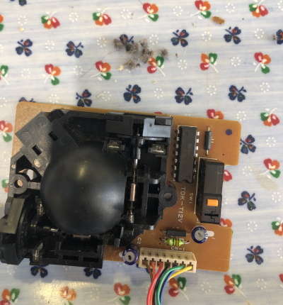
It is always a good idea to test the mouse before reassembly. In this case I got too excited about how great it turned out and just put it back together:
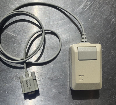
It is a beautiful thing! Testing showed it worked quite well. Sometimes these ball mice never really come back to good working order but in this case it was fantastic.
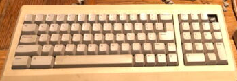
Keyboard
Next lets move onto the keyboard. The design of this is lovely. Sure it is a chunky unit but I love the look of it and the key action is awesome. The unit here is missing a * key top right, whcih is a shame but lets see how it behaves:
There is a copy of Microsoft Works on the system disc so lets make a document and test the keyboard:
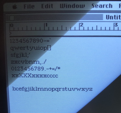
Almost perfect. We have a couple of naughty keys, A and D are not working… (Confused, it is almost as if the original user was playing first-person shooters all the time… Which it impossible)
Turning over the circuit board the next step is to identify the offending keys to get them desoldered. These will need to be opened up and see if they can be repaired:
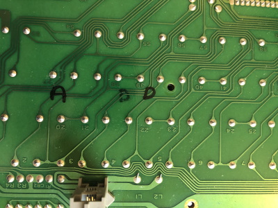
Yes, the faint looking D was the wrong switch… I need to be more careful. Desoldering these and pushing the keys off it realy easy. The switch mechanism can be dissasembled:
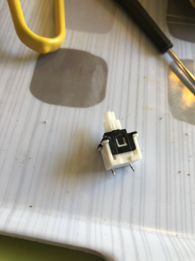
The sides of the switch can be gently opened up and slid apart:

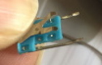
Internally these connectors are pushed to the side by the plunger. The contact is pushed to the side and makes a connection with the pins that out of the side. Using a pin and some steady hands you can gently prise the pins out of the recess, so they make better continuity:
Here is a diagram showing how this works:
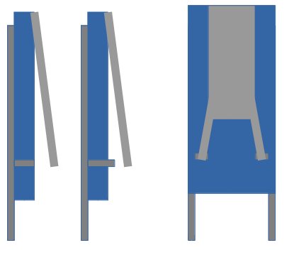
The left image shows the pin being drawn out a bit to that it is higher than the plastic hole. The right shows the contact that is pushed by the plunder. Lets test it with a simple meter:
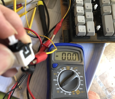
When pushed you can zero Ohmes which is fantastic! An easy fix. You can still get these switches but if they can be fixed as they are, at least to extend their lifespan then so much the better. Soldering them back into the board is easy it is time to test it. Opening up the same Works document lets try that again:
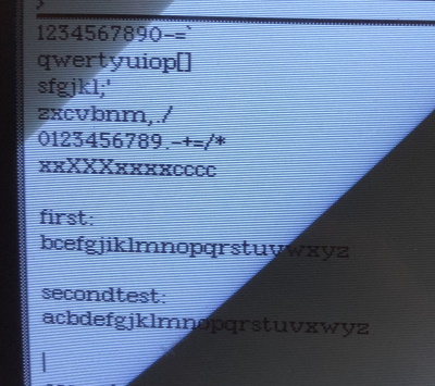
Success. We have a A and D key, ready for action! Lets check the state of the case and do some clean-up.
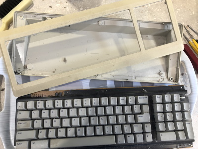
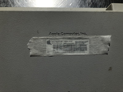
Using masking tape again for the label on the back, some warm water and washing up liquid transforms it into something you might want to type on.
The next step is to look into the transient CRT issue, review the software, future upgrades and more.